This page introduces basic GUI concepts for Flipper Zero development and reviews existing GUI application approaches with their pros and cons:
An asynchronous event handling mechanism that eliminates the need for polling or waiting for events (e.g., button presses, packet reception). Instead, event handler functions are assigned and invoked upon event occurrence, allowing the main loop to perform other tasks concurrently.
The canvas is just a raw drawing area with no abstractions over it. Drawing on the canvas directly is useful for implementing custom design elements (e.g., in games), but this is rather uncommon.
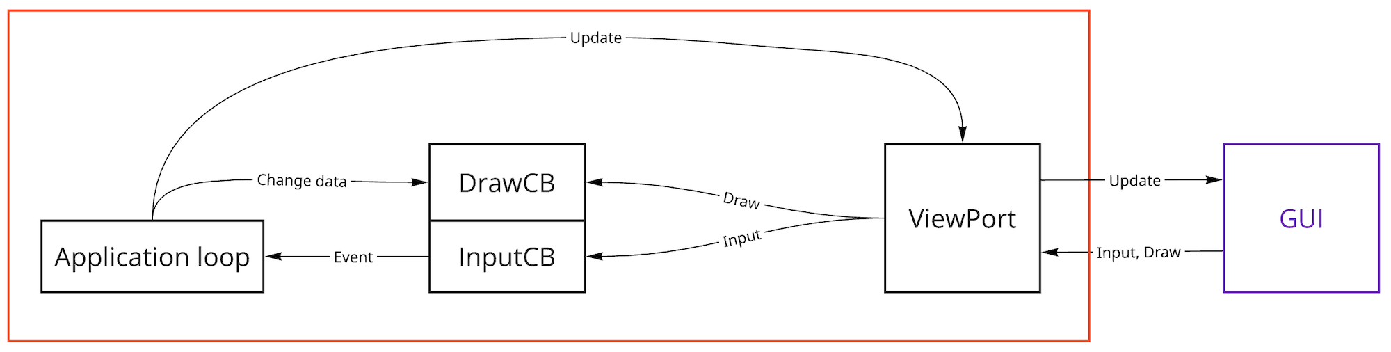
ViewPort defines the behavior and rendering of a screen area with specific position and size.
Multiple ViewPorts form a Drawing Stack, rendered bottom to top. This allows ViewPorts to overlap each other.
Displaying a specific ViewPort can be enabled or disabled after its creation.
The Model and View concepts help separate GUI from data, simplifying development, maintenance and testing.
The Model contains the data; technically, it is a structure in memory.
The View implements the logic for interface rendering and event handling. The View uses the Model: it retrieves data from the Model for display and modifies the data when processing events.
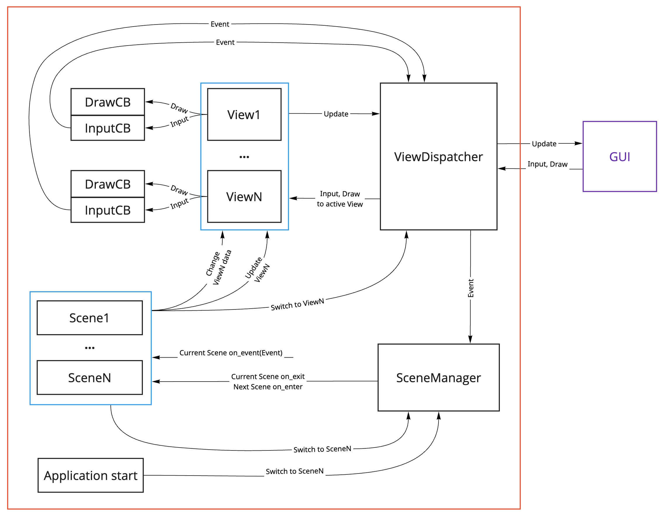
To switch between multiple views, there is a separate entity — the View Dispatcher, which holds references to all the views that an application needs and switches between them as requested by the application.
View modules are fullscreen templates (View+Model) included in the firmware for typical Flipper Zero UIs. Available view modules:
button_menubutton_panelbyte_inputdialog_exempty_screenfile_browserloadingmenunumber_inputpopupsubmenutext_boxtext_inputvariable_item_listwidgetView module source code: https://github.com/flipperdevices/flipperzero-firmware/tree/dev/applications/services/gui/modules
A Scene manages the behavior of an application within a single screen. For example, the standard GPIO application include the following screens:
gpio_scene_start (start menu)gpio_scene_usb_uart (USB-UART bridge mode interface)gpio_scene_usb_uart_cfg (USB-UART bridge mode settings interface)gpio_scene_usb_uart_close (confirmation dialog for exiting USB-UART bridge)gpio_scene_test (GPIO manual control)From the main menu, you can navigate to the manual control scene or enter USB-UART bridge mode. Within USB-UART bridge mode, you can access mode settings or exit the mode via a confirmation dialog.
Each scene implementation includes:
on_enter function: used to initialize the scene’s views.on_exit function: used to de-initialize the scene and free resources.on_event function: handles incoming external events.An external event handler can trigger a UI switch to another scene. For example, selecting an item in the main menu triggers a transition to the corresponding scene via the Scene Manager, which enables switching between scenes and simplifies navigation in applications with complex navigation flows.
In this section, we will review existing GUI development approaches, starting from the simplest and progressing to more complex ones. The complexity of the interface you want to create determines the number of GUI abstractions required.
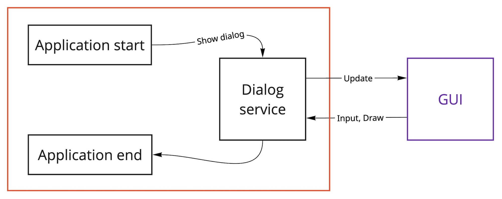
The simplest approach to building a GUI application. It is suitable when the entire interface can be implemented using only dialogs.
You can find the Dialog API functions in the header file dialogs.h.
Pros:
Cons:
This approach enables drawing on the screen and handling all button input. A single fullscreen ViewPort is created to render the display and process all events (e.g., button presses).
Pros:
Cons:
This is the main approach for developing applications with complex, hierarchical UIs. Most Flipper Zero applications use this method.
Pros:
Cons:
 1.12.0